
Develop pneumatic circuit to operate indirect single acting cylinder
Objectives :
- Understand : Understand operation of direction control valve
- Understand : Understand actuationmeans of direction control valve
- Apply-Select : Select the components required to operate pneumatic cylinder
- Evaluate-Design : Design the pneumatic circuit to operate single acting cylinder
- Evaluate-Design : Design the pneumatic circuit to operate double acting cylinder
Pneumatic control systems can be designed in the form of pneumatic circuits. A pneumatic circuit is formed by various pneumatic components, such as cylinders, directional control valves, flow control valves, pressure regulator, signal processing elements such as shuttle valve, two pressure valve etc. A pneumatic circuit diagram uses pneumatic symbols to describe its design.
Service units:
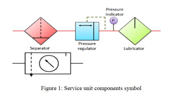
During the preparation of compressed air, various processes such as filtration, regulation and lubrication are carried out by individual components. The individual components are: separator/filter, pressure regulator and lubricator. Preparatory functions can be combined into one unit which is called as 'service unit'. Figure 1, shows symbolic representation of various processes involved in air preparation and the service unit.
Valve are defined as devices to control or regulate the commencement, termination and direction and also the pressure or rate of flow of a fluid under pressure which is delivered by a compressor. Valves used in pneumatics mainly have a control function that is when they act on some process, operation or quantity to be stopped. A control function requires control energy, it being desirable to achieve the greatest possible effect with the least effort. The form of control energy will be dictated by the valve's mode of actuation and may be manual, mechanical, electrical hydraulic or pneumatic.
Valve available for pneumatic control can be classified into four principal groups according to their function:
- Direction control valve
- Non return valves
- Flow control valves
- Pressure control valves
Direction Control Valve:
In order to control the movement of air actuators, compressed air has to be regulated, controlled and reversed with a predetermined sequence. Pressure and flow rates of the compressed air to be controlled to obtain the desired level of force and speed of air actuators.
The function of directional control valve is to control the direction of flow in the pneumatic circuit. DCVs are used to start, stop and regulate the direction of air flow and to help in the distribution of air in the required line.
Valves are represented by symbols because actual construction is quite complex. A symbol specifies function of the valve, method of actuation, no of ports and ways. Pneumatic symbols have been standardised in ISO 1219-1:2006. (Fluid power systems and components - Graphic symbols and circuit diagram). Another standard ISO 1219-2:1995 establishes the rules for drawing diagrams of fluid power systems using symbols from ISO 1219-1. Port designations are described in ISO 5599.
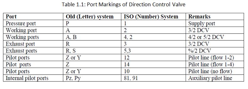
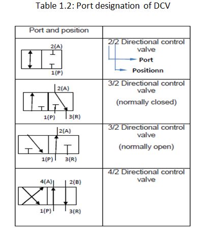
Ports and position: DCVs are described by the number of port connections or ways they control. For example: Two way, three - way, four way valves. Table 1 shows the Port markings of DCVs.

SPOOL DIRECTION CONTROL VALVES:
A. Hand operated 3/2 DCV
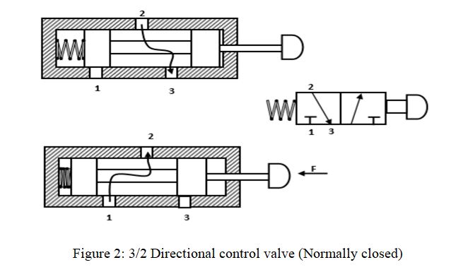
The cross sectional views of 3/2 DCV (normally closed) based on spool design is shown below. When the valve is not actuated, port 2 and 3 are connected and port 1 is blocked. When the valve is actuated then port 2 and 1 are connected and port 3 is blocked.
Figure 2, shows schematic diagram of 3/2 spring operated valve. There are three ports common port, normally open port and normally closed. When the valve is not actuated, there is flow from NO port to common port. When the valve is actuated there is flow from NC to common port.
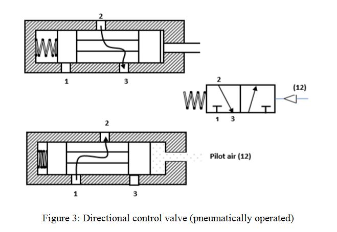
B. Pneumatically actuated 3/2 DCV
The cross - sectional views of pneumatically actuated NC type 3/2 DCV in normal position and actuated positions are shown in the Figure 3. In normal position, the working port (2) is closedthe pressure port (1) and open to the exhaust port (3). When the compressed air is appliedthrough the pilot port (12), the spool is moved against the spring. In the actuated position, the working port (2) is open to the pressure port(1) and closed to the exhaust port(3). Thus, the application of the compressed air to the port 12 causes the pressure port (1) to be connected to the working port (2).
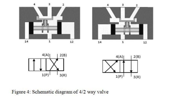
C.Pneumatically actuated 4/2 DCV
The valve shown in Figure 4, is a 4/2 way valve pneumatically operated DCV. Switch over is achieved by direct application of pressure. If compressed air is applied to pilot spool through control port 12, it connects port 1 with 2 and 4 is exhausted through port 3. If the pilot pressure is applied to port 14, then 1 is connected with 4 and line 2 exhausted through port 3. On disconnecting the compressed air from the control line, the pilot spool remains in its current position until spool receives a signal from the other control side.
METHODS OF ACTUATION:
The methods of actuation of pneumatic directional control valves depend upon the requirements of the task. The types of actuation vary;
- Manually actuated
- Mechanically actuated
- Pneumatically actuated
- Electrical
- Combined actuation
The symbols of the methods of actuation are detailed in DIN ISO 1219. When applied to a directional control valve, consideration must be given to the method of initial actuation of the valve and also the method of return actuation. Normally these are two separate methods.
INDIRECT CONTROL OF SINGLE ACTING CYLINDER
This type of circuit (Figure 6) is suitable for large single cylinders as well as cylinders operating at high speeds. The final pilot control valve is actuated by normally closed 3/2 push button operated valve. The final control valves handle large quantity of air. When the push button is pressed, 3/2 normally closed valve generate a pilot signal 12 which controls the final valve thereby connecting the working medium to piston side of the cylinder so as to advance the cylinder. When the push button is released, pilot air from final valve is vented to atmosphere through 3/2 NC - DCV.

The signal pressure required can be around 1-1.5 bar. The working pressure passing through the final control valve depends on the force requirement which will be around 4-6 bar. Indirect control as permits processing of input signals. Single piloted valves are rarely used in applications where the piston has to retract immediately on taking out the set pilot signal.